USB 2.0 is a widely used interface in today’s digital environment. Although many people use it in their daily lives, few are familiar with its performance requirements and specifications. This post will examine the performance requirements and cable characteristics of USB 2.0 based on the standard specifications provided by the USB IF (Implementers Forum). Additionally, we will use diagrams to explain these specifications clearly.
1. Propagation Delay
The propagation delay of a USB 2.0 cable is defined as a maximum of 26ns. This refers to the time it takes for a signal to travel between the two ends of the cable assembly. As the cable length increases, this value can also increase. This limitation is an important factor in ensuring transmission speed and maintaining cable performance. If the propagation delay becomes too long, it can interfere with data transmission. Therefore, it must be kept below a certain threshold.
2. Propagation Delay Skew
Propagation delay skew is used to verify whether the D+ and D- line signals arrive simultaneously at the receiver. This value is limited to a maximum of 100ps and plays a crucial role in situations where signal synchronization is critical during data transmission. If the D+ and D- signals do not arrive simultaneously, it can cause data transmission errors. Thus, the propagation delay skew value should be minimized.
3. Attenuation
Attenuation refers to the degree to which a signal weakens as it travels through a cable. For USB 2.0, the attenuation is specified as follows:
Maximum -1.90 dB at 100 MHz
Maximum -3.20 dB at 200 MHz
Maximum -5.80 dB at 400 MHz
This indicates that higher frequencies experience greater signal attenuation. When signals weaken, the accuracy of data transmission can decrease. Therefore, the cable must maintain the signal at an appropriate level.
4. Differential Mode Impedance
Differential mode impedance is a standard used to verify whether the signal lines of a cable maintain the appropriate impedance. For USB 2.0, this value is defined as 90Ω ± 15%. This specification is crucial for reducing signal reflection or loss during data transmission, thereby improving transmission reliability. If the cable’s impedance is too high or too low, signal loss can occur.
5. Common Mode Impedance
Common mode impedance is specified as 30Ω ± 30% and is necessary to minimize interference that may occur in the common mode. If the common mode impedance is not appropriate, interference during signal transmission through the cable can degrade data quality. Thus, common mode impedance is an essential factor in cable design.
6. Voltage Drop
The voltage drop of a USB 2.0 cable must not exceed 125mV. This value is specified based on a 5V, 500mA output. If the power delivered through the cable is insufficient, connected devices may not function properly. Excessive voltage drop can prevent devices from receiving the power they need. Therefore, meeting this specification is critical for ensuring stable power delivery.
7. Shield DC Resistance
Shield DC resistance is a crucial factor in determining the shielding performance of a cable. The resistance values vary depending on the AWG (American Wire Gauge). For example:
28 AWG: 1.16Ω
20 AWG: 0.18Ω
Thicker cables have lower resistance values. Lower resistance enhances the cable’s shielding performance, protecting data from external electromagnetic interference.
The table below provides a concise summary of these performance requirements.
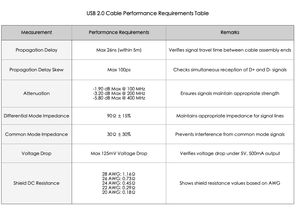
This table clearly illustrates the standards that USB 2.0 cables must meet to maintain reliable and stable transmission performance.
In conclusion, USB 2.0 cables may appear to be simple wires, but they incorporate various technical requirements to ensure high-speed data transmission and stable power delivery. The combination of these components and specifications enhances reliability, and understanding these standards can help in selecting more dependable USB cables.